The PitNode Pico Touch Extension Board (PitNode PTEB) is a PCB intended as a developer board for a Raspberry Pi Pico 2W.
What it provides
- 3 audio jacks (2.5mm) as inputs for probes to Picos internal ADCs and a ADC reference voltage regulator
- One K-Type thermocouple connector connected to Pico via a measurement amplifier and SPI
- Header sockets for connecting Touch LCD display via SPI
- USB-C connector for 5V DC power input (only power not for programming)
- A buzzer connected to a Pico PWM channel for sound alarms (beep)
There is also a 3D printed case for the extension board available.
The Gerber files and schematics are available on the PitNode PTEB GitHub repository.
The PitNode Pico Touch Extension Board (PitNode PTEB) is intended as a DIY developer board for hobbyists and makers. Assembly and use are at your own responsibility.
This is not a finished consumer product, but a hardware building block intended for DIY projects and experimentation.
See “Legal” for more information.
How to get it
With the provided files in the GitHub repository you can order the PCB wherever you want.
Check also the licensing information on PitNode PTEB GitHub repository.
Parts needed
Here is the BOM of the PitNode Pico Touch Extension board:
| Reference | Qty | Value |
|---|---|---|
| A1 | 1 | 2.8″ Touch LCD AZ Delivery |
| A2 | 1 | RaspberryPi_Pico_2W 2350 |
| BZ1 | 1 | CPT-1625-80-SMT-TR |
| C1,C2,C3,C4 | 4 | 100n |
| D1 | 1 | MBR120VLSF |
| J1 | 1 | XE1109-001 |
| J3 | 1 | 2.54mm Pin Socket 14 pol. 8mm height |
| J4,J5,J6 | 3 | SJ-2524-SMT-TR |
| J7 | 1 | UJC-HP-3-SMT-TR |
| Q1 | 1 | AO3401A |
| R1,R2,R3,R4,R5,R6,R7,R8,R12,R13,R14 | 11 | 33 |
| R9, R11 | 1 | 100 |
| R10 | 1 | 10k |
| R15,R16,R19 | 3 | 18k for 100k NTC 10k for 10k NTC |
| R17,R18 | 2 | 5k1 |
| R20,R21 | 2 | 10k |
| U1 | 1 | MAX6675ISA |
| U2 | 1 | LM4040DBZ-3 |
| U3 | 1 | FM24V01A-GTR, Optional at the moment |
| Spacer | 8 | Spacer M3 12mm distance between PCB and display and top cover, 6mm screw |
| Screw | 4 | M3 x 15mm countersunk head screw |
| Nut | 4 | M3 |
| Washer | 4 | M3 |
| Thread inserts for 3D prints | 8 | Ruthex M3x5,7 |
| PCB PitNode Pico Touch EB | 1 |
And of course you need tools for SMD soldering.
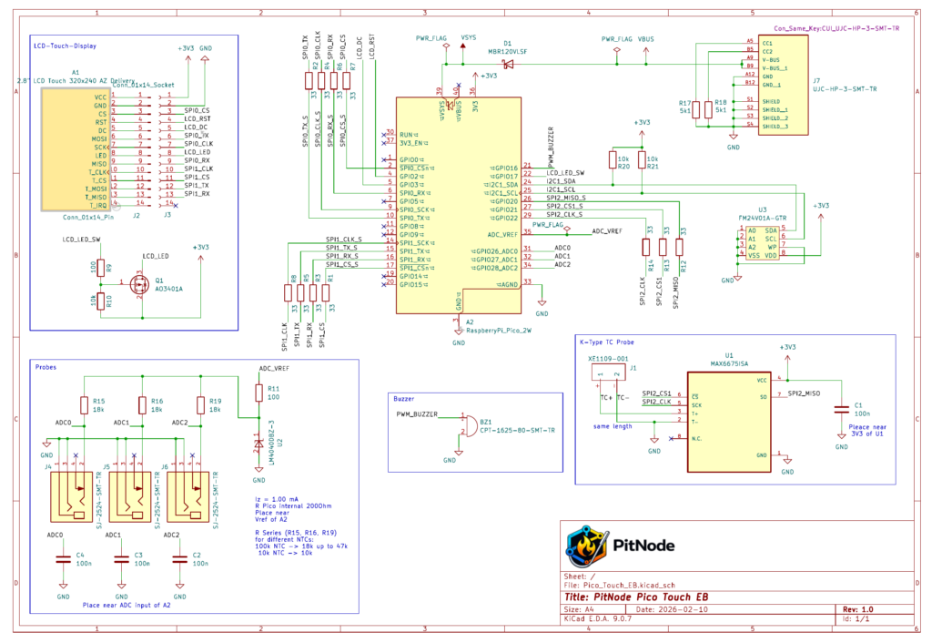
Schematics
The following picture shows the schematics
Assembly instructions
If you choose a professional PCB manufacturer based on the design I provided, then you will get a PCB with silkscreen and solder mask. This makes the assembly steps much easier.
This project assumes SMD soldering experience. There are many excellent SMD soldering tutorials available online.
I have some recommendations regarding the order of soldering.
- USB-Connector:
Start with soldering of the USB connector. My experience was that this is the toughest part to solder. The pads are small and the pitch is tight. I recommend to use flux for soldering the USB connector.
When you mastered this part, the hardest solder task is done!
To make sure that you do not have a unwanted short just check with a simple multimeter the resistance between the USB pins.
You shall have a connection between the GND connections (A12, B12, S1, S2, S3, S4) and another connection between V-Bus connections (A9, B9). - Shottky Diode:
Now we solder the Shottky Diode D1. Make sure that the cathode is on the correct pad. So the cathode line on the part is towards the direction of the Pico.
If this is ok then plug in a USB-C cable to a USB power supply. Then measure the voltage at Pin 39 (VSYS) on the Pico footprint. You should have about 5V there. If this is all ok, then continue. - MAX6675:
Next part is the thermocouple amplifier MAX6675. Make sure Pin 1 marker om the IC is aligned correctly with the Pin 1 marker on the silkscreen. - FM24V01A-GTR:
This part is a chip storage based on FRAM technology. It is not yet used by the SW but in near future. So you can decide if you want to use it or not. - Now you can solder all resistors and capacitors. There is no polarization to care about.
- Then we solder the audio jacks and the buzzer to the PCB.
Make sure that the audio jacks have a good solder joint because they need to withstand some force to plug in the probe. - Now mount the K-Type thermocouple connector. The thick pins need some heat in order to get a good electrical and mechanical connection.
- If this is all ok, then we continue with soldering the Pico itself. You need a Pico with header pins!
Just insert the Pico with USB connector looking towards the PCB USB connector. Make sure that the Pico does not move when you turn the PCB to solder it from the bottom side. Solder all pins. After soldering of all wires, cut the too long wires on the bottom side. - The last step is to solder the Pin socket for the touch display. I recommend to plug the pin socket on the LCD display’s pin header. Then mounting the display with the spacers on the PCB.
The advantage is that the pins are aligned accurately and can not fall out when you turn the PCB again in order to solder it. - Now you need to install the spacers at the position of the 4 “inner” holes of the PCB. Fix them with nuts and washers from the bottom side of the PCB.
- If you use the 3D printed case you need to mount the Ruthex thread inserts to the bottom part the the case.
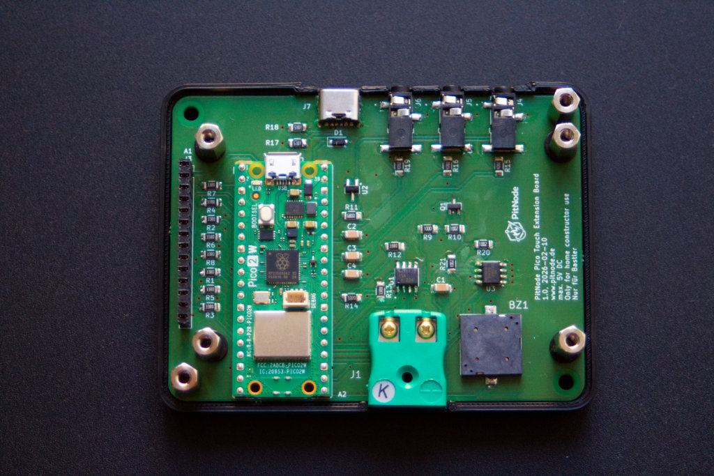
Follow the instructions of Ruthex. - Now you can use the 4 outer spacer to fix the PCB on the case (in the picture of the prototype I used 2 fixation points only).
- Before you mount the display and cover of the case, make sure you did the installation process.
- Now mount the display by plug it onto the pin header and fix it with 4 screws.
- The cover is screwed with countersink screws from the top into the spacer.
Leave a Reply